


DFI X48 UT-T3RS Motherboard

Motherboard Layout
Â
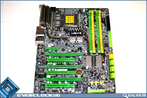
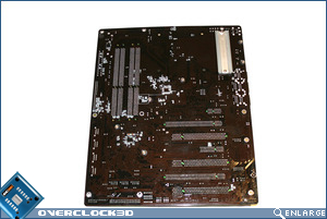
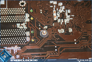
The motherboard itself is typical of DFI with the trademark UV reactive PCI slots. However that is not what dominates the board this time around. The gorgeous heatsink assembly from Thermalright is perhaps the most eye catching aspect of the board. A black PCB is now a prerequisite for enthusiast boards and the DFI is no different. On the back of the motherboard we see that it is relatively clear save for a heatsink! Yup thats right, a heatsink is actually on the back of the board. To be fair this heatsink is actually a backplate adding support for the MOSFET area but credit to DFI for adding a few fins even though I doubt the thermal properties of a PCB will aid heat dissipation! A nice idea nonetheless.
Â
Â
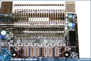
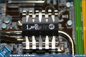
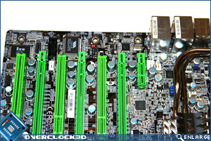
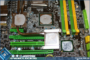
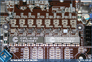
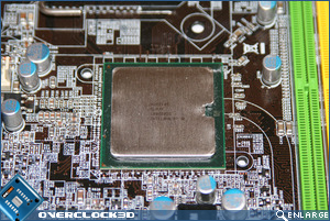
Starting from the top of the board, we see that the CPU socket area is relatively sparse which is good news for the extreme coolers out there. This is due to the Volterra 8 Phase digital PWM which claim to be up to twenty percent better than traditional PWM. Again, Thermalright take charge of cooling down the PWM area with a huge heatsink and also include a separate ‘Flame Freezer’ additional heatsink which we will cover later in more detail.
Â
Â
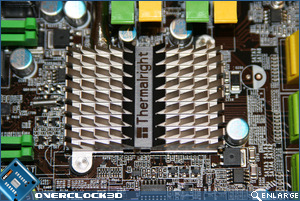
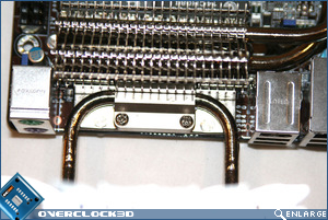
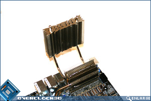
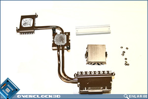
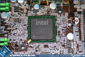
The PWM heatsink is attached via a heatpipe to the Northbridge heatsink, which in turn is attached to the Southbridge as a single unit. The heatsinks themselves are Aluminium and are of typical Thermalright design being both great looking and perhaps more importantly functional. The NB/SB heatsinks are however a lot more ‘chunky’ than the PWM one with thick fin spikes that would be more akin to some sort of torture device rather than motherboard cooling! The fins are angled 45 degrees to increase the cooling area and are attached to the motherboard via a screw design rather than push-pins which ensure a very solid and tight fit as well as an even mount. Surprisingly DFI elected not to use backplates on these which, due to the screw-down version of fitment, could warp the board should excessive pressure be applied.
Â
Â
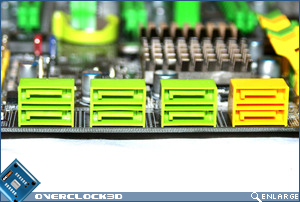
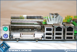
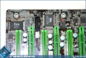
The DFI offers a host of connectivity with 8 SATA ports, allowing a massive amount of storage should you feel the need. 6 of the ports (green) are Intel and the two Yellow ports belong to the JMicron. Personally I always found Intel to perform much better than the JMicron ports so would have preferred there to be Intel across the board but the addition of 2 JMicron ports does allow you to use a separate controller should you feel the need. It is a welcome option nonetheless. Towards the back of the board we find the I/O area where there is a gaping gap. This is where the Flame Freezer fits which may be why DFI have not included the amount of USB ports we have become accustomed to with high-end boards of late. The connectivity is all there though with 2 Gigabit LAN ports, 6 USB ports, a Firewire port and the traditional PS/2 mouse and keyboard sockets.
Â
Â
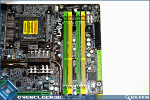
The PCI slots are all UV lime green with right to left (top to bottom) PCIe 1x, PCIe 16x, PCI, PCIe 4x, PCI, PCIe 16. Obviously being an X48-based motherboard, Crossfire support is fully supported at its maximum bandwidth of 16+16 lanes. It should be noted that there is a mistake in the labelling in the manual regarding the PCIe slots positioning. In the manual it describes the centre slot as PCIe 16x where in fact it is 4x and it actually shows the bottom PCIe slot as 16x. The layout is near as damn perfect allowing the use of 2 dual slot GPU’s while still allowing access to a single PCIe x1, the 4x PCIe slot (Raid/physics?) and PCI slot should you require them. The PCIe slots have 4-pin floppy cable headers which are not required unless you intend on running Crossfire. The manual does, however, suggest using them should you take advantage of Crossfire as it will supply more power to the board and grant a more stable system.
Â
Â
The Lanparty UT X48-TS3R requires a minimum of a 300W PSU (DFI recommend a 400W). Personally I think that unless you are running a very low spec system (which would negate buying a high-end motherboard!) then a PSU double that being recommended would be the wisest choice.Â
Â
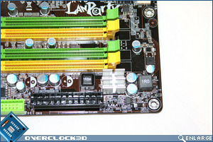
The board’s PSU socket areas are 24+8pin which is pretty much standard in today’s market. Q-tec users should look elsewhere I’m afraid.
Â
Â
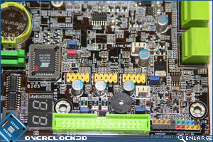
Above right we see a very cluttered area. DFI have once again utilised the on-board switches we have become to know and love. The power and reset switches can operate individually (power/reset) or can operate together to clear the CMOS after a dodgy overclock. This does away with the need for a further CMOS clear switch freeing up space for other items, such as the Diagnostic LED. While useful (you will come to hate the ‘C1’ error!), it would have been nice of DFI to actually include in the manual what each error/readout is as there is nothing to be found in the manual. But with a quick search on DFI’s excellent support forums most codes can be found with ease.
Â
Moving along we see DFI still retain the use of a floppy and on-board speaker. It is nice to see the DFI also retain the removable BIOS chips which will no doubt help in restoring the motherboard to a workable state by an easy BIOS chip swap should it become corrupt. The board also has a variety of Jumpers which do everything from selecting the FSB of your CPU, to clearing the CMOS and even selecting the power requirements of your USB, of which there are an additional 3 headers but sadly no included bracket to make use of them. Â
Â
Â
Motherboard Cooling
Â
Being a DFI, it’s pretty obvious that this board is aimed squarely at the overclocker. Overclocking inevitably leads to heat and DFI have taken this into consideration when designing the board and so drafted in the help of Thermalright. Starting with the PWM area I mentioned earlier, the ‘Flame Freezer’, which for all intents and purposes is an extension of the cooling assembly which extends out of the case. The fitments are pretty much self explanatory by the use of a coupling bracket held on by two screws but if you are in any doubt then DFI do supply a mini instruction booklet for your perusal.
Â
Remember I mentioned the backplate? Well now you see why it is required as I’m sure you can imagine that knocking the flame freezer while fumbling around the back of the PC case for a USB slot could quite easily snap the PCB. The backplate therefore serves to strengthen that area.
Â
Â
Perhaps the most ingenious thing about the whole heatpipe setup is the inclusion of an adaptable Northbridge. You can actually remove the Northbridge without the need to remove the whole heatpipe assembly. This is a great idea as you can add your own cooling to the Northbridge sink, be it water or air. The top is removed by the means of a clip very similar to AMD CPU coolers. Both surfaces are machined flat and have a dull finish but this shouldn’t impact on the heat transfer of the blocks. Big thumbs up DFI!
Â
Â
Most folk would stop there as to be quite honest the removal of the whole heatpipe assembly is not required unless you wish to watercool each component individually. Here at OC3D we like to go that one step further and have done exactly that:
Â
Â
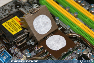
As all the heatsinks are screw down affairs, it was a time consuming process not made any easier by the fact only the Northbridge had screw heads. The nuts on the rear are also a pita to remove as they are ‘sealed’ with some gunk to prevent unwanted loosening. Once the heatpipe was removed we can see that surface contact on all of the components was near perfect with just the right amount of paste being used.
Â
Â
So the board is as near to perfect you are going to get and is probably the best cooled motherboard out on the market at this moment in time. Everything is in the right place and with the ultimate amount of configuration options available via jumpers and the diagnostic readouts by both the main LED and individual LED’s situated around the motherboard. It is clear that this motherboard can certainly talk a good fight. Let’s now take a look at the means by which we can activate some of those LED’s with, what I expect to be, a ridiculously complex BIOS as per DFI tradition.